Until recently, all of the techniques (for example GNSS) we have used to measure surface deformation were based on detecting the changes at specific points on the ground. We can never be sure that we are seeing a whole picture of deformation, or that we aren’t missing small-scale deformation, of our monitoring networks. About twenty years ago, InSAR (Interferometric Synthetic Aperture Radar) technology as an effective tool for ground deformation monitoring burst on the scene. Scientists around the world were struck by the details visible in the image as one of the most essential advantages of InSAR technology is exploitation of an active radar systems. These are capable of providing high-resolution imagery independent of daytime (day/night) and weather. Radar interferometry is currently one of the fastest developing areas of the remote sensing. Progressive methods of this technology has become an important tool for topographic mapping and for precise measurements of deformation of the Earth’s surface and man-made structures. InSAR techniques are effective in the geophysical monitoring of natural hazards (earthquakes, volcanic activity, landslides and subsidence), in the observation of dynamic components of the Earth’s surface, in generation of digital elevation models, in land cover classifications and environmental surveys.
How radar interferometry works?
InSAR is a remote sensing modality for analysing radar images obtained by the satellites that are carriers of Synthetic Aperture Radar (SAR). The radar antenna continuously transmits microwaves towards the Earth’s surface and record waves reflected back to the antenna position. Energy of the received signal contains a pair of important information, which compose radar images: amplitude and phase of backscattered electromagnetic waves. The former one contains information about how much of the wave bounced back off to the satellite (signal intensity). This depends on how much of the wave has been absorbed on the way and how much has been reflected in the direction of the satellite. The second information is the phase of the wave. The phase information plays a significant role also in other geodetic measurement methods (e.g terrestrial distance measurement by phase-shift rangefinder, GNSS positioning, etc.). When a wave travels through the space, we can think of it as a hand on a clock. It starts on 1200 when the wave leaves the satellite. The ‘hand’ (phase) keeps running round and round the clock until the wave reaches the ground. When the wave hits the ground, the hand stops indicating certain ‘time’ or ‘phase’. When the wave comes back to the satellite, it tells the satellite on what value the hand got stopped. Every point in a satellite image (pixel) is carrying those two information: the intensity and the phase. The intensity can be used to characterize the composition of the surface the wave bounced off and what orientation it has. Oil leaks on the sea, for instance, can be spotted in that way. They look much smoother than the water surrounding as their intensity is different from intensity of the water. The phase is used in another way. When the radar satellite revisits the exact same portion of the Earth, the phase image should be identical. If it is not the case, then something has been going on. By combining those two images, we can measure how much and where the ground has moved.

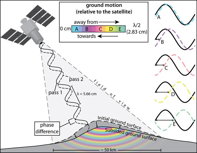
Fig.1: Principle of radar interferometry. Source: volcano.si.edu
Interferometric exploitation of observed data requires processing of at least two radar images covering an identical territory. Therefore, data acquisition requires double registration of exactly same part of the Earth’s surface. By comparing the phase components captured in different times, it is possible to calculate deformations which had occurred between sensing periods. The very first radar interferometry technique utilized for the ground deformation monitoring is called Differential InSAR (DInSAR). General principle of this method lies in the use of at least two radar images of the same area that are acquired at different times. By connecting one image to another it is possible to distinguish changes that occurred during the time interval between their acquisitions. Changes or surface deformations are represented by areally distributed information here.
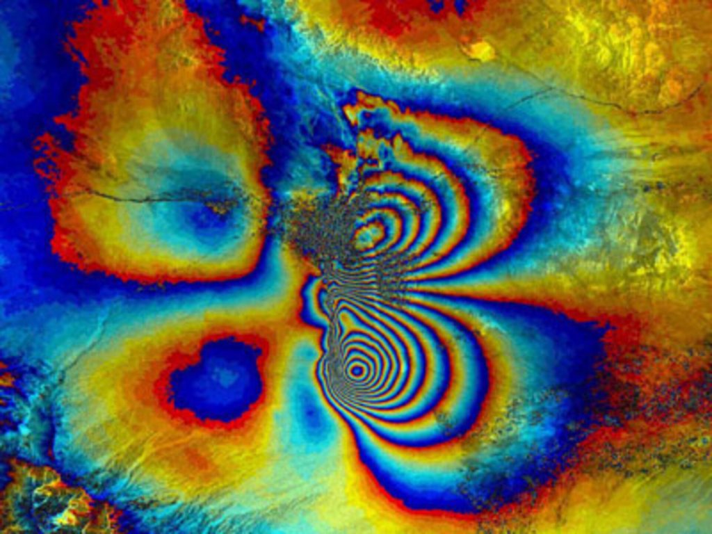
Fig. 2: The Differential Interferogram of the Bam Earthquake (Iran). Source: esa.int
Combining two separate radar images of the same scene highlights the alterations in the scene with radar waves backscattered from the ground features having a different signal phase, manifesting in colourful interference patterns on the combined image known as fringes. These fringes can be used to measure tiny changes in the landscape down to a maximum accuracy of a few millimeters. Interferogram shows coseismic deformation in wrapped fringes (2.8 cm per color cycle), which are similar to contour lines of the ground motion, measured from the satellite radar imagery. The ground moved both towards the satellite in the south-east quadrant (colour scale change from +π to – π) and away from the satellite in the north-east quadrant (colour scale change from -π to +π).
The problem occurs when this information contains reflection of the radar waves from a ground element which, although changing, cannot be interpreted as the deformation (eg. vegetation change, variation in atmospheric conditions). For this reason, Multi Temporal InSAR (MTI) algorithm was developed. The MTI approach utilizes only reliable and stable in time (permanent/persistent) scattering ground elements. The deformation here will be revealed only in a set of significant points, where the theoretical accuracy can be lower than 1 mm (!).
Multi Temporal InSAR techniques
Satellite radar interferometry (InSAR) utilises microwave signal transmitted towards the Earth’s surface. A moving radar antenna onboard satellite transmits and simultaneously records a signal reflected back to the satellite’s position. The “phase” of the received signal is the primary component for the deformation analysis. Images are taken in certain times (T1 ,T2, …,Tn) in order to extract precise deformation time series over each man-made object. The “phase” of the signal is basically the measure of the change in satellite-to-target distance (R1, R2, …, Rn) from the first until last (n-th) acquisition of the satellite over the same area (Fig. 3).
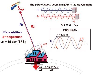
Fig. 3: Principle of the satellite radar interferometry (InSAR) (T1 ,T2, – time of the acquisition, R1, R2, – satellite-to-target distance in different T, ΔR – measured change in satellite-to-target distance) Source: researchgate.net
In multi-temporal InSAR (MTI) techniques, resulting deformations are revealed in a dense set of a significant points. Multi-temporal InSAR technique is advanced method of satellite radar interferometry which utilises only reliable and stable in time scattering ground elements for millimetric precision movement estimation. The backscattered signal from these points shall be stable and constant for a longer periods. Therefore, MTI techniques are suitable for deformation monitoring in urban areas, as buildings and other urban elements are good reflectors of radar waves and changes or subsequent deterioration of reflected signal is smaller. Such features are widely available over a city, but less present in non-urban areas. The measurements here should be repeated exactly under the same conditions in order to reach millimetric accuracy in movement estimation. Phase stable points, can be used as a ”natural GPS network” to monitor terrain motion, analysing the phase history of each one.
The formidable advantage of space-borne Interferometric Synthetic Aperture Radar (InSAR) is to monitor tiny displacements simultaneously over wide areas (whole cities in one image), in high resolution (up to 25 cm using X-band data such as TerraSAR-X or Cosmo-SkyMed) frequently every 12 days or 6 days (up to 12 hours) without the need for in-situ observations or special equipment in the areas of interest, while providing accuracy similar to the traditional or terrestrial techniques (e.g. levelling or GPS). InSAR as a remote sensing modality could complement and even outperform ground-based measurements, which in some cases tend to under-sample the displacement field in spatial (GPS antennas are available only at specific points) or temporal (e.g. low frequency of levelling measurements) domain. Nevertheless, there are important limitations associated with the application of InSAR measurements e.g.:
- minimum number of images required for the processing (~20 images) what can increase overal the cost of analysis while exploiting commercial data,
- deformation from one orbit track is measured only in the line-of-sight of the satellite,
- geometric distortions of radar images (shadow) might represent difficulties in mountainous areas and,
- lower (or none) sensitivity to very rapid or large changes (built-up areas, construction works), especially those exceeding phase detectable in one pixel (for Sentinel-1A/B it’s ~0.5 cm a day)